Simulation of a common-source circuit using SOCAD and ADE-L
This tutorial demonstrates how to use SOCAD to simulate a common-source circuit on Cadence Virtuoso from a Python program. It uses the files provided in the project example.
SOCAD is divided in two programs:
- The first program is designated as SOCAD server (for simplification). It is responsible to make the bridge between Cadence Virtuoso and the SOCAD client, executing the tasks required by the SOCAD client and returning the results from Cadence.
- The second program is designated as SOCAD client. It is responsible to control the Cadence behavior (e.g. update circuit variables values, run simulation, …), and to receive the simulation results.
1. Design the circuit and configure the simulation environment
This circuit was designed with the STM 65nm technology, using Cadence Virtuoso IC6.1.7-64b.500.15 and the ADE-L environment.
1.1. Design the circuit
The common-source (CS) circuit is shown below.
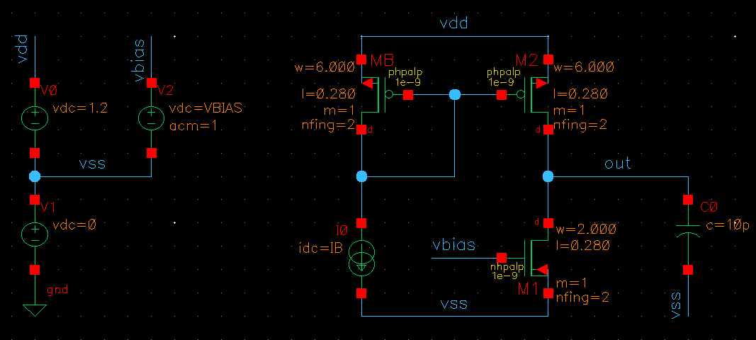
After designing the circuit, the circuit parameters to be updated by the SOCAD client need to be associated with variables (e.g. width of transistor M1 is named W1, biasing current is named IB, and so on). For this specific circuit, the author defined the following variables:
| Parameter | Description |
|---|---|
| W1 [um] | Width of the transistor M1 |
| W2 [um] | Width of the transistors M2 and MB |
| L [um] | Length of all transistors |
| IB [A] | Biasing current of the current-mirror |
| VBIAS [V] | Biasing voltage of the transistor M1 |
1.2. Configure the simulation environment using ADE-L
The ADE setup is highly circuit-dependent, and for this circuit is the following:
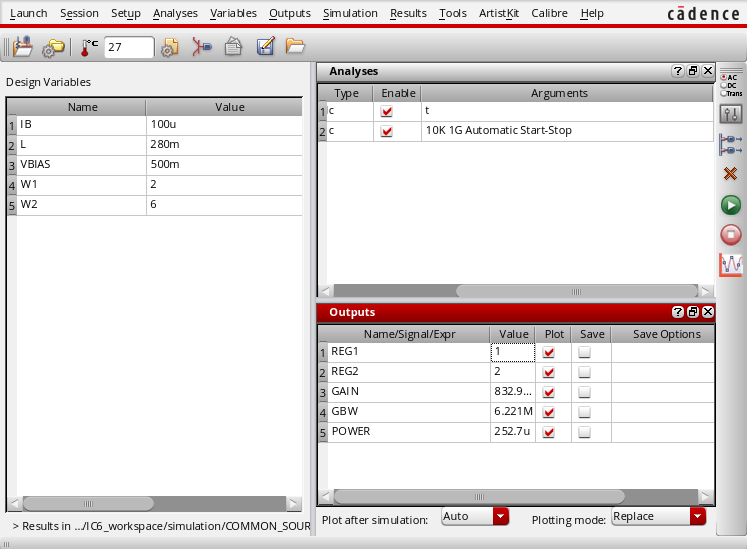
These are the steps performed to achieve the state shown in the figure:
- Import the variables to the ADE-L (Variables -> Copy From Cellview).
- Define the analysis to perform. In this example the author chose:
- DC - to get the transistors’ operating regions, and the overall power consumption;
- AC - to get the circuit gain and GBW.
- Set the simulation outputs, as following:
- GAIN -
ymax(mag(v(\"/out\" ?result \"ac\")) - REG1 -
pv(\"M1.m1\" \"region\" ?result \"dcOpInfo\") - REG2 -
pv(\"M2.m1\" \"region\" ?result \"dcOpInfo\") - POWER -
(- pv(\"V0\" \"pwr\" ?result \"dcOpInfo\")) - GBW -
gainBwProd(mag(v(\"/out\" ?result \"ac\"))) || 0.0
- GAIN -
The DC outputs (REG1, REG2, POWER) are easily obtained from the Tools -> Results Browser… menu, and the AC outputs (GAIN, GBW) can be obtained from the Tools -> Calculator….
In the GBW output, the expression ends with || 0.0. This sub-expression indicates that the GBW default value is 0.0 (with type = float), i.e. if the simulator can’t obtain the GBW value, it will assign zero to GBW. This prevents simulation errors that can broke the program.
After setting the ADE-L environment, perform a simulation and be sure that there are no errors and the simulation outputs are correctly displayed. It’s also recommended to save the environment state.
2. Generate the OCEAN scripts
The OCEAN scripts are executed by Cadence, when requested by the SOCAD client, and include commands to load the simulator, run a simulation, update the circuit variables. These files are obtained from the ADE-L state that was configured in Section 1
This is the trickiest part of the configuration. This step comprises two main tasks:
- Export an OCEAN script with the ADEL-L configurations.
- Split the previous file in three scripts:
- Load the simulator (in this example is Spectre) (loadSimulator.ocn);
- Load the circuit variables before run a simulation (run.ocn);
- Run a simulation and save the outputs to a file (vars.ocn).
2.1. Export the OCEAN script
The OCEAN script with the ADE-L configuration can be exported from Session -> Save Ocean Script …. For the circuit of this example, it content is the following:
simulator( 'spectre )
design("CADENCE_WORKSPACE/simulation/COMMON_SOURCE/spectre/schematic/netlist/netlist")
resultsDir("CADENCE_WORKSPACE/simulation/COMMON_SOURCE/spectre/schematic" )
modelFile(
    '("CADENCE_WORKSPACE/nominal/spectre/nominalwrapper.scs" "")
)
definitionFile(
    "models.scs"
)
analysis('ac ?start "10k"  ?stop "1G"  )
analysis('dc ?saveOppoint t  )
desVar(       "IB" 100u     )
desVar(       "L" 0.28      )
desVar(       "VBIAS" 500m  )
desVar(       "W1" 2        )
desVar(       "W2" 6        )
envOption(
    'analysisOrder  list("dc" "ac")
)
temp( 27 )
run()
GAIN = ymax(mag(v("/out" ?result "ac")))
plot( GAIN ?expr '( "GAIN" ) )
REG1 = pv("M1.m1" "region" ?result "dcOpInfo")
plot( REG1 ?expr '( "REG1" ) )
REG2 = pv("M2.m1" "region" ?result "dcOpInfo")
plot( REG2 ?expr '( "REG2" ) )
GBW = (gainBwProd(mag(v("/out" ?result "ac"))) || 0.0)
plot( GBW ?expr '( "GBW" ) )
POWER = (- pv("V0" "pwr" ?result "dcOpInfo"))
plot( POWER ?expr '( "POWER" ) )
2.2. Split the OCEAN script in multiple files
These files are available provided with the project exemple under the socad_cadence -> script directory.
2.2.1. loadSimulator.ocn
This script includes the definition of the simulator (spectre), the netlist and results directories, the file with the devices models, and the analysis to perform. One only needs to load this file once per program execution, usually at the begin of the program.
; Set up the number notation, precision, etc, of the results
setup(?numberNotation 'engineering)

; Simulator and design folders
simulator( 'spectre )
design("CADENCE_WORKSPACE/simulation/COMMON_SOURCE/spectre/schematic/netlist/netlist")
resultsDir("CADENCE_WORKSPACE/simulation/COMMON_SOURCE/spectre/schematic" )
modelFile(
    '("CADENCE_WORKSPACE/nominal/spectre/nominalwrapper.scs" "")
)
definitionFile(
    "models.scs"
)

; Analysis to perform
analysis('ac ?start "10k"  ?stop "1G"  )
analysis('dc ?saveOppoint t  )
envOption(
    'analysisOrder  list("dc" "ac")
)

; Other settings
temp( 27 )
The only parameter that is not included in the original script file is the setup(?numberNotation 'engineering), which changes the number notation to engineering. More info about this command can be found in the Cadence help documentation [CDCHELP].
2.2.2. run.ocn
This file runs the simulation, get the results and store them in the SOCAD_RESULT_FILE.
run()   ; run a simulation

; Output file
out_file = getShellEnvVar("SOCAD_RESULT_FILE")
outf = outfile(out_file "w")

; Simulation results
GAIN = ymax(mag(v("/out" ?result "ac")))
REG1 = pv("M1.m1" "region" ?result "dcOpInfo")
REG2 = pv("M2.m1" "region" ?result "dcOpInfo")
GBW = (gainBwProd(mag(v("/out" ?result "ac"))) || 0.0)
POWER = (- pv("V0" "pwr" ?result "dcOpInfo"))

; Save results to file
fprintf( outf "%s\t%g\n", "GAIN", GAIN)
fprintf( outf "%s\t%d\n", "REG1", REG1)
fprintf( outf "%s\t%d\n", "REG2", REG2)
fprintf( outf "%s\t%g\n", "GBW", GBW)
fprintf( outf "%s\t%e\n", "POWER", POWER)

close(outf) ; Close the file
The format specifiers (e.g. %d) of the fprintf function must be chosen according to the respective result’s data type. In doubt, one can use the function float(<result>) to convert the result to float, and then use the %f or %g specifier. If the wrong specifier is provided, the Cadence will trigger an error. More info about the used functions can be found on the Cadence help documentation [CDCHELP].
2.2.3. vars.ocn
This file includes the circuit design variables.
desVar(   "IB" 100u    )
desVar(   "L" 0.28     )
desVar(   "VBIAS" 500m )
desVar(   "W1" 2       )
desVar(   "W2" 6       )
3. Run the program
The program is started in two steps:
- Start the SOCAD server, which should be located in the machine where Cadence Virtuoso is installed.
- Start the SOCAD client, which can be in any machine that reach the SOCAD server, or in the same machine, depending to the chosen socket type (more info about the sockets can be found in the Library Reference).
NOTE: It is mandatory to run the SOCAD server before the SOCAD client!!!
3.1. SOCAD server
3.1.1. Configure the server
The SOCAD server configurations are in the file start_cadence.sh located in the directory socad_cadence from the project example. This file is responsible to create the required variables, directories and files, and runs Cadence Virtuoso. The following variables can be changed by the user:
SOCAD_PROJECT_NAME="project_example"- project name and directorySOCAD_WORK_SPACE="/home/example/project_ws"- project work space, i.e. the directory that contains the project directory.SOCAD_CLIENT_ADDR="localhost"- IP address of the SOCAD client.SOCAD_CLIENT_PORT="4000"- port of the SOCAD client.
3.1.2. Run the server
- Copy the directory socad_cadence, located in the project example, to the machine where Cadence Virtuoso is installed.
- Replace the files in the socad_cadence/script folder for the ones generated in Section 2.2.
- Run the start_cadence.sh script with the command
sh start_cadence.sh. If it’s the first time that the program is executed for a project, the folder SOCAD_WORK_SPACE/SOCAD_PROJECT_NAME described in Section 3.1.1. is created and the folder socad_cadence/script is copied to that folder. If further modifications to the scripts are required, they should be made in the new script folder, i.e. SOCAD_WORK_SPACE/SOCAD_PROJECT_NAME/script.
If the program is started successfully, the terminal should present the following message in the last line:
[INFO] Cadence is connected to server! Waiting for a connection from the client...
This means that the SOCAD server is connected to Cadence Virtuoso and is waiting for a connection from the SOCAD client.
3.2. SOCAD client
3.2.1. Configure the client
The SOCAD client configurations are only regarding the SOCAD server IP and port, and can be modified on the main() function of the socad_example.py module on the project example, where:
host = "localhost"- IP address of the SOCAD server.port = 4000- port of the SOCAD server.
3.2.2. Run the client
The SOCAD client is executed with the command python socad_example.py. If the program is started successfully, the terminal output should be similar to:
mdmfernandes@EXAMPLE:~socad/example$ python socad_example.py

<license header>

Starting client...
Connecting to server...
[INFO] Connected to server with the address 127.0.0.1:46434

############### SOCAD EXAMPLE ###############
1 - Load simulator
2 - Update variables and run a simulation
0 - Exit.

-> Please Select:
This means that the SOCAD client is connected to the SOCAD server. The SOCAD server also displays an info message:
[INFOs] Connected to client with address 127.0.0.1:51912
4. Running example
This section shows a typical execution of SOCAD. After starting both the SOCAD server and SOCAD client successfully, one may load the simulator and then run simulations.
NOTE: The simulator should de loaded before running a simulation, otherwise Cadence will trigger an error and the program will terminate. Also, this can erase all circuit variables from the vars.ocn file.
4.1. Load the simulator
The simulator is loaded from the file loadSimulator.ocn, through Cadence Virtuoso, after choosing the option 1 on the SOCAD client. If everything goes well, Cadence sends the message loadSimulator_OK to the SOCAD server. When the SOCAD server receives this message, it sends the circuit design variables, stored in the file vars.ocn, to the SOCAD client. The SOCAD client terminal output is similar to:
############### SOCAD EXAMPLE ###############
1 - Load simulator
2 - Update variables and run a simulation
0 - Exit.

-> Please Select: 1

Simulator loaded with success! Received variables:
Variable: VBIAS - Value: 0.55
Variable: IB - Value: 0.00011
Variable: L - Value: 0.308
Variable: W1 - Value: 2.2
Variable: W2 - Value: 6.6
4.2. Update variables and run a simulation
To simulate that the circuit design variables were updated (e.g. by a circuit optimizer), the SOCAD client increases their value by 10% when it receives the simulation results from the SOCAD server.
By selecting the option 2 on the SOCAD client, the Cadence will start a simulation (the simulation log is shown on the SOCAD server terminal output). If the simulation is successful, it sends the message updateAndRun_OK to the SOCAD server, which in turn sends the simulation results, stored in the file SOCAD_RESULT_FILE, to the SOCAD client. The SOCAD client terminal output is similar to:
############### SOCAD EXAMPLE ###############
1 - Load simulator
2 - Update variables and run a simulation
0 - Exit.

-> Please Select: 2

Sending updated variables...
Key: VBIAS - Val:0.5
Key: IB - Val:0.0001
Key: L - Val:0.28
Key: W1 - Val:2.0
Key: W2 - Val:6.0

Received updateAndRun from Cadence
Simulation results: {'GBW': 6221070.0, 'REG2': 2.0, 'GAIN': 0.832934, 'POWER': 0.0002527307, 'REG1': 1.0}
4.3. Exit from SOCAD
By selecting the option 0 on the SOCAD client, both SOCAD and Cadence Virtuoso are terminated. The SOCAD server terminal outputs the message Server has stopped with the exit code 0. I'm out!!! and the SOCAD client terminal outputs the message **** Closing socket and ending program... Bye! ****.